
Flanges are a vital and critical component in fluid transmission piping and industrial equipment connections. In the oil, gas, petrochemical, marine, and steel industries, using appropriate flange types in accordance with international standards is essential to ensure safety and equipment longevity. In this article, we review common industrial flange types—including Weld Neck, Slip On, Blind, Lap Joint, and Socket Weld—and explain pressure classes 150, 300, 600, 900, 1500, and 2500.
1.Introduction to Flange Types
1.1 Weld Neck Flange
This flange features a tapered hub that smoothly transfers stresses to the pipe. It is suitable for high-pressure and high-temperature applications.
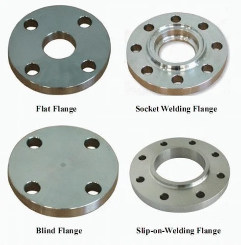
1.2 Slip-On Flange
This type of flange slides over the pipe and is then welded in place. It offers easy installation but is intended for medium-pressure applications.
1.3 Blind Flange
A blind flange has no center opening and is used to seal the end of a pipeline or an open valve. It is ideal for pressure testing or terminating piping runs.
1.4 Lap Joint Flange
In this design, a loose flange is placed over a stub-end, allowing quick assembly or inspection without disconnecting the pipe.
1.5 Socket Weld Flange
Similar to the Slip-On type, this flange has a socket into which the pipe is inserted before welding. When welded with a small, precise fillet weld, it is excellent for small-bore industrial piping.
2.Pressure Classes
Pressure classes are standardized ratings that define flanges and fittings from Class 150 up to Class 2500. The class number approximately indicates the maximum allowable working pressure in pounds per square inch (psi):
| Pressure Classes | Approximate psi | Description |
|---|---|---|
| 150 | 2000 psi | Low to medium pressure |
| 300 | 3600 psi | Light oil and gas industries |
| 600 | 7200 psi | High pressure, main lines |
| 900 | 10500 psi | High pressure in refineries |
| 1500 | 17500 psi | Very high-pressure applications |
| 2500 | 29000 psi | Very high pressure; high-pressure/high-temperature applications |
The higher the pressure class, the greater the thickness of flanges and bolts/nuts.
3.Flange Type and Pressure Class Combination Review
3.1 Weld Neck (Class 150–2500)
- Class 150–300: Suitable for medium temperature and pressure
- Class 600–1500: Used in refineries and critical gas/oil areas
- کلاس ۲۵۰۰: برای فشار و دمای بالا بهویژه در خطوط استاتیکی پالایشگاهی و بخار
3.2 Slip On (Class 150–300)
- Class 150: For water, steam, and gas connections at low pressure
- Class 300: Used in light refineries or medium lines
3.3 Socket Weld (Class 150–600)
- From Class 150 to 600 on small-diameter lines (under 2 inches), because it provides more precise installation
- Suitable for systems where leakage sensitivity is important
3.4 Lap Joint (Class 150–300)
- Usually used in lower classes
- For lines that require frequent opening and closing
3.5 Blind (Class 150–2500)
- Used for end caps or line terminations
- In pressure test projects, all classes can be used
4.Correct Flange Selection Based on Application
4.1 Pressure and Temperature
For high temperature and pressure, heavy flanges such as Weld Neck with higher classes (600 and above) are used. For low to medium pressure, Slip On or Socket Weld is sufficient.
4.2 Fluid Type
For corrosive fluids such as acid, seawater, or natural gas, stainless steel or special alloy flanges are commonly used. The pressure class must match the material specification.
4.3 Line Accessibility
For lines that may need to be opened quickly (test lines), Blind or Lap Joint is a suitable option.
4.4 Thickness and Allowable Space
High pressure requires greater thickness; Class 1500 or 2500 flanges are very thick and have larger bolts/nuts, so sufficient space must be available on site.
5. Standards and Guidelines
Flange usage must be carried out in accordance with recognized standards:
- ASME B16.5: For flanges Class 150 to 1500
- ASME B16.47: For large-diameter flanges
- API 6A: For very severe oil and gas conditions
- DIN EN: European standard
Materials must also be selected according to ASTM, EN, or API standards, and after machining, welding and testing must be performed.
6. Manufacturing and Quality Control Steps
6.1 Initial Cutting and Forming
Stainless steel or carbon steel plates are cut and machined to specified diameters.
6.2 Precision Machining
Flange surfaces are faced to ensure accurate hole and ring positioning, and parallelism and angle are maintained.
6.3 Welding (if required)
For flanges such as Socket Weld or Lap Joint, minor welding is performed, followed by PT and MT testing.
6.4 Quality Control Tests
Testing steps include:
- Dimensional testing: checking thickness, diameter, holes
- Leakage testing: on pressure lines
- Hydrostatic pressure testing: to ensure integrity
- Weld NDT testing: PT, MT, or RT to verify weld points
7. Flange Selection in Lirab Sanat Projects
Based on experience and the variety of industrial projects, companies such as Lirab Sanat provide flanges according to project requirements. For example:
- Weld Neck flanges Class 600 and 1500 for refineries or steam lines
- Stainless steel Slip On Class 300 for marine industries
- <Socket Weld with ferritic alloy material for medium-pressure lines (2 inch)
- Blind Class 1500 for closing line ends with the ability to test without removing the flange
- Lap Joint for equipment requiring frequent servicing
🔚 Summary
Flange types are selected based on connection type, operating pressure, temperature, and fluid type. Weld Neck and Slip On flanges are the most commonly used types, but for special applications such as test lines or high pressure, Blind, Lap Joint, and Socket Weld types play a specific role.
Pressure classes from 150 to 2500 define the required thickness and standards to be followed. Correct flange selection increases service life, reduces maintenance costs, and enhances reliability in industrial projects.